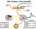
Wiring diagram for the popular Eldred Esquire mod (also known as the "cocked wah" effect). This setup makes the most of a single pickup guitar using typical Telecaster components (3 way switch, volume, tone etc...). The video demonstrates how to assemble this setup yourself and the detailed photo guide below takes you through the process step by step.

Esquire Eldred Mod Switch Controls:
Switch position #1. This rear position is the same as on a standard Esquire. The pickup goes through the volume control only, with the tone control bypassed for a hotter, louder lead sound with added highs.
Switch position #2. This middle position is also the same as on a standard Esquire, with the pickup going through both the volume and tone controls. It sounds a little warmer than position #1.
Switch position #3 In the front position of the Eldred Esquire wiring setup, the pickup goes through a single, small capacitor (0.0047uF) and the volume control, with the tone control once again bypassed. It removes the fixed treble roll-off network and replaces it with the capacitor. This offers an extra dimension and more flexibility and gives what is popularly known as the "cocked-wah" effect.
You will need
- 2 x 250k potentiometers
- 1 x CRL 3 way blade switch
- 1 x 0.047uF capacitor
- 1 x 0.0047uF capacitor
- Switchcraft jack socket
- Gavitt cloth wire
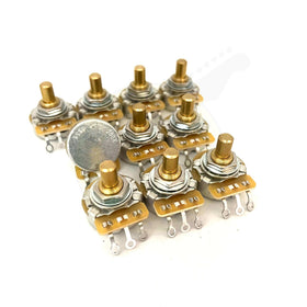
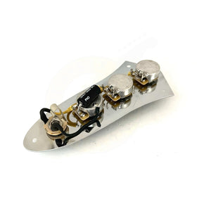
The above components are all available in our electronics section or in the form our of Esquire wiring kit.

Step One - Capacitor and Grounding
We will start with our tone capacitor which allows us to ground the volume pot lug at the same time.
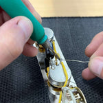
Our capacitor goes from the output (middle) lug of the tone control and the other end goes to ground. One way to do this is to feed it through the volume pot lug, solder it in place, and run the end of the wire to ground on top of the pot casing. We now have a functioning volume control and a functioning tone control. Refer to the below photo.

Step Two - Fixed 0.0047uF capacitor
Before continuing, familiarise yourself with the below solder lug numbers on the 3 way switch. Lugs 1 - 8 (where 4 and 8 are the common lugs).

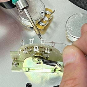
For the fixed 0.0047uF capacitor which is used for position 3 when playing, we need to one lead of the capacitor to lugs 5 and 3. As we have done in the below photos, it is useful to use the cap lead itself to make these connections by feeding it through lug 5 and hopping across to lug 3.

Solder the other end of the capacitor to ground, typically on top of the volume pot casing.

Step Three - Connecting the Tone Control
Next, we need to connect our switch to the tone control. As in the previous step, we need to run a wire that connects lug 6 to lug 2. Using cloth wire, run the wire up through lug 6 and across to lug 2, soldering both in place.

Connect the other end of this wire to the third lug of the tone control.

Step Four - Switch
Back to the switch, we now need to connect it to the volume control. Basically we achieve this by running a continuous wire from the common lugs to the volume input lug on the pot.
You can do this whatever way you prefer, but we like to push the cloth back on some cloth wire and run it from lug 7, direct next to it onto lug 8, then across to lug 1 and then finally to lug 4. Refer to the below photos.


Finally, using a second length of cloth wire, connect lug 4 to the volume input lug.

Step Five - Jack Socket
Before we can put everything back into the guitar we need to wire and connect the jack socket.
Identify what lug does what - the inner ring (sleeve) is the ground and the tip is our hot/signal lug.

Solder black cloth wire to the ground lug and cream/yellow wire to the signal lug. Use what ever colour you prefer of course - it is just generally accepted that black is ground.
Bend the wire round for a better mechanical connection before soldering in place. Ideally you want the wire to be in contact with both sides of the solder lug. Your ground connection on the jack socket is the most important ground in the circuit.
We always use heat shrink tubing on jack sockets and like to twist the wires tightly together. This is optional of course and not essential - but wrapping the ground wire around the signal wire helps protect the signal wire from unwanted EMI (electro-magnetic interference).
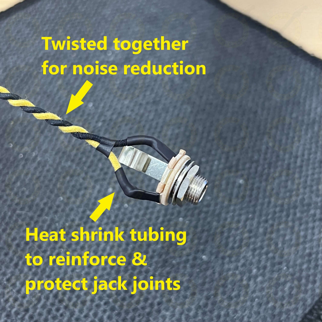
Solder the ground wire from the jack to ground on the circuit. Typically this will be either on the tone or volume pot casing. We put ours on the tone control purely for space saving but either works fine. Solder the signal wire to the output of the volume control (middle lug).

Now we can put our control plate back into the guitar. It is important to ensure we have a ground connection from the bridge (and therefore the strings) and the circuit. Typically this is done on Telecaster/Esquire models with a ground wire that sits underneath the bridge which is then kept securely in place once the bridge is screwed flat to the body.

Solder the end of this main ground wire to the top of the volume pot casing with the pickup ground. You can either twist them together and solder them together to the pot, or you can solder them seperately.

Finally, connect the pickup signal wire to lug 8 on the switch (the common lug).

That is how to wire the popular Eldred mod in an Esquire. Refer to the video and familiarise yourself with the diagram before getting started. You can of course play around with different capacitor values to tweak the circuit to your tonal preference. The fixed capacitor on the switch does need to be lower value - the tone control itself you can choose anything you want really, ranging from 0.1uF (dark) to 0.015uF (bright). Typically, 0.047uF or 0.022uF are the most used.
Telecaster Wiring Diagrams
Wiring in Series (with push pull pot)
1 Single Coil, 1 Volume, 1 Tone
HS Telecaster Wiring (Humbucker/Single Coil)
Guitar Wiring Guides
